
Contents
STM32G0 LPUART Bare-Metal (No HAL)
Bare-metal LPUART is something I began learning when I decided to build a recovery beacon for my university rocketry team.
I had 3 spare STM32G031K8 Nucleo boards and wanted to see how far I can push a small battery to allow the MCU to keep transmitting its GPS coordinates at regular intervals until we recover the rocket (for the mid-2027 launch, so if you're reading after that, hopefully the launch went well!)
Naturally, using UART's low-power alternative, LPUART, was the obvious move.
At its core, both the regular UART and the LPUART peripherals implement the same protocol to achieve the same thing, the difference is their execution. That's why if you've read the UART article (which was STM32H7RS-specific), you'll already know a lot of the information around how UART works and what the main parts of the block diagram are, so you might want to just skim them and hurry to the part about the differences.
What Is UART?
UART stands for Universal Asynchronous Receiver-Transmitter. It's a universal way of receiving and transmitting serial data, serial meaning it's sent one bit at a time instead of at once.
In short, 2 connected devices send and receive packets between each other through their own ‘transmit' and ‘receive' lines, and they do it at a pre-agreed speed.
The packet itself is structured so the receiver knows when it starts, how much data there is, a bit to check if the data is corrupted, and another 1 or 2 to know that the packet is finished.
2 devices are connected with 2 physical lines (device A's transmit connects to device B's receive, and device B's transmit connects to device A's receive). These lines are used to send/receive packets at a pre-agreed speed (called baud rate).
Packets are structured, generally like this:
- 1 bit indicates the start of a packet
- 7-9 bits (configurable) hold the data
- 1 bit (optional) indicates if the data is corrupted via bit parity
- 1 or 2 bits (configurable) signal the end of a packet
Parity
This is an optional bit that the receiver can use to detect if the data it received has been corrupted in transit (e.g. if the line is noisy or there's interference).
There are 2 options:
- odd parity
- even parity
In either case, the amount of 1's in the data are counted and the parity bit is set based off that:
- In odd parity, if the number of 1's is even, the parity bit is 1
- If the number of 1's is odd, the parity bit is 0
- Vice-versa for even parity
This isn't a perfect way of detecting errors - if 2 data bits are corrupted instead of 1, it will not be detected, but it's good enough for basic UART.
It's also not an error correction mechanism, it can only detect them.
Parity On STM32
On the STM32s, the parity bit is counted towards the total data bits. So if you've selected to have 9 data bits, and you enable the parity bit (done with the PCE bit in the LPUART_CR1 register), you will only have 8 bits for data; the 9th is reserved for the parity bit.
Stop & Start Bits
By default, the UART data lines (both the Tx and Rx line) idle at a logical high (AKA they idle at 1). This is why the start bit HAS to be the opposite of what the line idles at, else the start of a packet won't be reliably detectable. The stop bit is the same logical level as the idle line.
So for the default configuration, the start bit is 0 and the stop bit is 1.
Each of the Tx/Rx lines have a logical level inverter (LPUART_CR2 register, specifically the TXINV/RXINV bits) which inverts the polarity of the whole line, this making idle & start a 1, and stop a 0. All data is also inverted.
Oversampling On The G0
If you're interested in what oversampling is, look at the generic UART chapter - the LPUART doesn't support oversampling configurations so knowing what it is would only benefit your personal knowledge.
For the actual oversampling, there isn't any.
RM0444 outlines on page 1,084: "The receiver samples each incoming bit as close as possible to the middle of the bit-period. Only a single sample is taken of each of the incoming bits."
As a result of not having oversampling, there is also a lack of noise error detection* for the transferred data.
So if you are designing something that'll live in an environment where electrical noise is a real factor, UART may not be the best option even for unimportant data.
* The NE (Noise Error) flag still exists in the LPUART_ISR, it just can't be triggered by the 'data' part of the packet. More info later on
LPUART On The STM32G0
The main benefit of using LPUART over the USART controller on the G0 family is that it is capable of running UART at a 9,600 baud rate with just the LSE 32.768 KHz clock, which makes it possible to function in low-power modes by using the LSE as its kernel clock.
LPUART Block Diagram
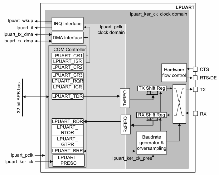
The hardware breaks down as follows:
- the
lpuart_pclkbus interface clock domain manages the register access for you to configure the LPUART - the
lpuart_ker_ckkernel clock domain manages the actual UART protocol logic and data transfer
On the left, you see all of the registers you use to configure and control the UART protocol, including things like interrupts and DMA. On the right, you see the actual execution of the protocol.
Character & Data Length
As I said in the explanation of what UART is, the LPUART controller lets you configure between sending 7, 8, and 9 bits of data per packet.
The control is done with the M1 and M0 bits in the LPUART_CR1 register, which means the lpuart_pclk bus interface clock must be turned on through the RCC_APBENR1/RCC_APBSMENR1 register for the LPUART instance you wish to control.
The stop bits are also configurable in the STOP bit field of the LPUART_CR2 register, letting you select between 1 and 2 stop bits.
The controller can also send 2 'special' characters:
- Break character: all bits from the start bit to the last stop bit are 0s, followed by 2 regular stop bits
- Idle character: all bits from the start bit to the last stop bit are 1s
What the receiver decides to do with these bits is user-defined.
Transmitting/Receiving Data
By default, the LPUART transceiver transmits/receives 1 data frame at a time, requiring you to service it every single time to avoid delays or overruns (when new data comes in before you read the old one, causing data loss).
It's done through 2 registers:
LPUART_TDRfor transferring dataLPUART_RDRfor receiving data
There are also flags (LPUART_ISR register) and interrupts associated with the flags which let you service the data on an interrupt basis instead of polling and blocking the CPU, but that's for the interrupt section.
LPUART FIFO Mode
If you want to only service data when you have a few bytes backed up instead of on every frame, the FIFO mode is one of the solutions.
By enabling it with FIFOEN in the LPUART_CR1 register, transceived data from the TDR/RDR registers is moved over to the FIFO, allowing the transmitter/receiver to service another data frame, then another, and another, until the FIFO is empty/full (empty for transmissions, full for receiving).
Once you set the FIFOEN bit, there's nothing else you need to do*:
- Writing to the TDR register pushes bytes to the TxFIFO and shift register automatically, so sending data is exactly the same
- Reading from the RDR register pulls bytes from the RxFIFO after the read, so receiving data is exactly the same
* Unless you want interrupts.
LPUART Interrupts
To avoid going over each individual interrupt, which will be in the table at the bottom of this section, here's what you need to know:
- Look for the
xxxIEbits in one of the control registers (CR1/CR2/CR3) - To enable the interrupt, set the bit
- To disable the interrupt, clear the bit
Once you set the bit (e.g. TXEIE), an interrupt will be generated when the corresponding flag is set in the LPUART_ISR register (for TXEIE that's the TXE flag - when the TDR register is empty). Note that if the interrupt is disabled, the flag is still set regardless, so your ISR needs to not only check for the set flag, but also its corresponding enable bit, something like this:
void LPUART_ISR(void)
{
    if ((LPUART->ISR & LPUART_ISR_TXE) && (LPUART->CR1 & TXEIE))
    {
        // TXE flag generated interrupt
        // ...
There is also a configurable threshold interrupt. You can set the interrupt to be generated when the TxFIFO drops below it, or the RxFIFO goes above it, that way you have time to service the data before hitting an overrun.
Transmitter Interrupts
| Flag | Meaning | How To Clear | How To Enable |
|---|---|---|---|
| TXE | Transmit data register empty | Write to TDR | TXEIE |
| TXFNF | Transmit FIFO not full | Fill TxFIFO | TXFNFIE |
| TXFE | Transmit FIFO empty | Write to TDR or write 1 to TXFRQ | TXFEIE |
| TXFT | Transmit FIFO threshold reached | Write to TDR | TXFTIE |
| CTSIF | Clear-To-Send interrupt | Write 1 to CTSCF | CTSIE |
| TC | Transmission complete | Write to TDR or write 1 in TCCF | TCIE |
Receiver Interrupts
| Flag | Meaning | How To Clear | How To Enable |
|---|---|---|---|
| RXNE | USART\_RDR not empty | Read RDR or write 1 to RXFRQ | RXNEIE |
| RXFNE | RxFIFO not empty | Read RDR until RxFIFO is empty or write 1 to RXFRQ | RXFNEIE |
| RXFF | RxFIFO full | Read RDR | RXFFIE |
| RXFT | RxFIFO threshold reached | Read RDR | RXFTIE |
| ORE | Overrun error detected | Write 1 in ORECF | RXNEIE/RXFNEIE |
| IDLE | Idle line detected | Write 1 to IDLECF | IDLEIE |
| PE | Parity error detected | Write 1 to PECF | PEIE |
'Other' Interrupts
| Flag | Meaning | How To Clear | How To Enable |
|---|---|---|---|
| NE | Noise error | Write 1 in NECF | EIE |
| ORE | Overrun error\* | Write 1 in ORECF | EIE |
| FE | Framing error | Write 1 in FECF | EIE |
| CMF | Character match\*\* | Write 1 in CMCF | CMIE |
| WUF | Wake-up from low-power modes | Write 1 to WUC | WUFIE |
* The OVRDIS bit in the USART_CR3 register has to be set to 0 for this flag to work as explained.
** A character match is the same as an address match, the UART block looks for incoming characters that match what's inside the ADD bits in the USART_CR2 register, triggering an interrupt when detected.
LPUART Clock Sources
Since STM32 implements its peripherals with a peripheral and kernel clock, you need to configure both for the LPUART to function fully.
Peripheral (Bus Interface) Clock
This is the one that starts to look like a spider web because there are just so many ways to configure it.
First, you need to figure out what your system clock speed (SYSCLK) is going to be, and that can be selected from the following sources:
- LSE
- LSI
- HSE*
- PLLRCLK
- HSI** The former 3 are unassuming - you just turn them on and adjust their speed (if applicable).
The latter 2, however, have a bit more depth. The PLLRCLK is specifically referring to the output of the 'R' divider on the PLL, as that's the only one of the dividers that can feed the generation of the system clock. The HSI is ran through a divider before it's muxed to act as the system clock. The divider is selected by the HSIDIV bits in the RCC_CR register.
Once you have your system clock (SYSCLK), there are a further 2 dividers it must run through before it touches the APB bus (and therefore your LPUART):
- AHB prescaler
- APB prescaler
Both of these are controlled in the RCC_CFGR register, by the HPRE/PPRE bits respectively.
And voila! We have our lpuart_pclk clock :)
* The G031K8 does NOT seem to have this on the Nucleo board by default, you need to attach/solder your own.
** HSI refers to HSI16 for the STM32G031K8, some families of the G0 also have a HSI48, which is primarily for USB and RNG, but the chip I'm using doesn't support it. Regardless, HSI48 doesn't get involved with the system clock generation so it'd be uninteresting for this article in any case.
Kernel Clock
The possible LPUART kernel clock sources are the following, and can be selected by the LPUARTxSEL bits in the RCC_CCIPR register:
- PCLK (same as the APB peripheral clock)
- SYSCLK (same as the system clock)
- HSI
- LSE
The former 2 are already covered in the peripheral clock part - PCLK is the final APB bus clock, the same one used for lpuart_pclk, whereas SYSCLK is the system clock before any AHB/APB prescalers get involved, also mentioned in the last subsection.
The latter 2 are just the direct clock sources from the oscillators. Yes, this includes HSI - it does NOT get the value divided by HSIDIV, rather the raw HSI speed, as confirmed by CubeMX experimentation.
Once you have this, it is also divided by the LPUART prescaler value, which is configurable via the LPUART_PRESC register.
And voila! We have our lpuart_ker_ck_pres clock :)
Error Detection
Framing Error
This occurs when the stop bit(s) are not correctly detected at the expected time, which will happen after a de-synchronisation or noise.
Using the interrupt tables above, this corresponds to the FE bit.
Despite the error, the data received in the shift register still goes in the LPUART_RDR register.
It's worth noting that if you're not using multibuffer communication (multiple MCUs talking to each other over the same Tx/Rx lines), this bit doesn't generate an interrupt, however since the data still goes in the RDR register, an interrupt is generated anyway by the RXNE bit.
Other Errors
The other errors are overrun and noise error.
Overrun was covered earlier - it happens when new data comes in the receiver's shift register before you've serviced the old one, leading to the loss of the old data.
Noise error was also mentioned, but the reference manual is very vague about this. Besides knowing it can't occur for the data part of a UART packet, there isn't a mention of what actually triggers it (or even how, if only 1 sample is taken per baud period).
I'd probably just avoid UART if noise is going to be an issue in your project anyway.
Baud Rate Generation
Firstly, for LPUART, automatic baud rate detection isn't supported like on the full implementations of the regular UART/USART peripherals.
This means you need to calculate and set your baud rate manually, and you must also know what baud rate the other device(s) are communicating at beforehand.
2 non-constant parts make up the calculation used by the LPUART controller to generate the baud rate:
lpuart_ker_ck_pres- LPUARTDIV
The former is just the clock the LPUART block receives, the section on clock selection further up outlines how it's calculated.
The latter is a value you decide on and write to the LPUART_BRR register. Its only limitation is that it must be at least 0x300 (768 in decimal), but there are also practical limitations:
- if using the LSE as a kernel clock source, the max baud rate is 9,600 (LPUARTDIV = 0x369)
- if using any other clock source, the clock speed must be between 3x and 4,096x the baud rate
The formula for calculating your baud rate is:
baud rate = (256 * lpuart_ker_ck_pres) / LPUARTDIV
Which can also be rearranged to get your LPUARTDIV value for the LPUART_BRR register:
LPUARTDIV = (256 * lpuart_ker_ck_pres) / baud rate
Clock Deviation
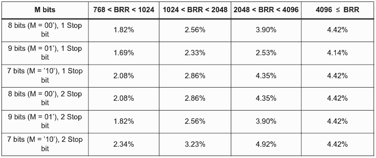
In order to avoid issues, the overall deviation of all sources has to be less than the maximum allowable LPUART deviation tolerance, which you can find in your reference manual for your specific board.
To calculate your actual deviation, you need to add up the following values, all as percentages:
- DTRA: deviation due to transmitter*
- DREC: deviation due to receiver*
- DQUANT: deviation from imperfect quantisation of receiver baud rate
- DTCL: deviation due to transmission line
- DWU: deviation due to sampling point moving around after a low-power wake-up (see formula below)
Here are the deviation tolerances for the STM32G0x1 boards:
Low-Power Management
This is what the LPUART was designed for, and it's standout feature.
Even when the bus interface clock (lpuart_pclk) is disabled, data receiving can still occur.
There are 2 cases when a wake-up request is generated to wake the MCU up from its low-power mode*:
- FIFO mode off: when the
LPUART_RDRregister is full, AKA when theRXNEflag is set - FIFO mode on**: when the TxFIFO is empty (
TXFEflag), the RxFIFO is full (RXFFflag), or the RxFIFO is not empty (RXFNEflag)
Alternatively, there is something called WUS which is a 2-bit field in the LPUART_CR3 register. Selecting a value from there and enabling the WUFIE bit in the same register will allow you to instead select one of these as a wake-up source:
- address match (explained in the generic UART article, I haven't copy-pasted it here yet)
- start bit detection
RXNE(which you can already do anyway using theRXNEIEmethod, though this will work even with FIFO on)
* All relevant IE bits must be set prior to entering low-power mode, as well as the UESM bit in LPUART_CR1 for the wake-up request to work as expected.
** You can also use this with the FIFO thresholds (TXFT/RXFT) if you want more time to service the data and avoid overruns.
Low-Power Notes
- Make sure you don't enter low-power modes with a transaction that's ongoing. Note that the
BUSYflag in theLPUART_ISRregister is NOT enough to determine this. Your best bet is probably hardware flow control, but that's a subset of UART I haven't documented properly yet, as it's technically under a different protocol name anyway - The
WUFflag from theWUSsource is set even when NOT in low-power mode - If entering low-power modes right after initialising the LPUART, wait for the receiver to actually be on via the
REACKbit inLPUART_ISR(note it does NOT have an interrupt associated with it)
Final Thoughts
This is honestly very similar to the regular UART, but it does fall under a separate controller with different capabilities compared to the full USART controller implementation on the STM32, so it was worth an article.
I'm going to go and write some LPUART drivers for my STM32G0 now...