
Contents
STM32 UART (Universal Asynchronous Receiver-Transmitter)
I began learning UART after a 2-day debugging nightmare on a small OLED screen. I wanted to learn I2C communication by printing text to it, but not matter what, it remained blank.
Eventually I solved it, but I could've saved 2 days if I knew how to just print debug statements from my STM32 to my computer.
UART itself is easy enough to learn, the implementation on an STM32 is what troubled me with its countless options and ways of implementing them.
What Is UART?
UART stands for Universal Asynchronous Receiver-Transmitter. It's a universal way of receiving and transmitting serial data, serial meaning it's sent one bit at a time instead of at once.
In short, 2 connected devices send and receive packets between each other through their own ‘transmit' and ‘receive' lines, and they do it at a pre-agreed speed.
The packet itself is structured so the receiver knows when it starts, how much data there is, a bit to check if the data is corrupted, and another 1 or 2 to know that the packet is finished.
2 devices are connected with 2 physical lines (device A's transmit connects to device B's receive, and device B's transmit connects to device A's receive). These lines are used to send/receive packets at a pre-agreed speed (called baud rate).
Packets are structured, generally like this:
- 1 bit indicates the start of a packet
- 5-9 bits (configurable) hold the data
- 1 bit (optional) indicates if the data is corrupted via bit parity
- 1, 1.5, or 2 bits (configurable) signal the end of a packet
Parity
This is an optional bit that the receiver can use to detect if the data it received has been corrupted in transit (e.g. if the line is noisy or there's interference).
There are 2 options:
- odd parity
- even parity
In either case, the amount of 1's in the data are counted and the parity bit is set based off that:
- In odd parity, if the number of 1's is even, the parity bit is 1
- If the number of 1's is odd, the parity bit is 0
- Vice-versa for even parity
This isn't a perfect way of detecting errors - if 2 data bits are corrupted instead of 1, it will not be detected, but it's good enough for basic UART.
It's also not an error correction mechanism, it can only detect them.
Parity On STM32
On the Nucleo-STM32s, the parity bit is counted towards the total data bits. So if you've selected to have 9 data bits, and you enable the parity bit (done with the PCE bit in the USART_CR1 register), you will only have 8 bits for data; the 9th is reserved for the parity bit.
Stop Bits
Hold on - 1.5 stop bits???
Yup, that's one of the first things which confused me. On certain hardware or when the 2 devices have slightly different clock speeds due to hardware limitations, the stop bit may need to be longer than 1 so the receiver can properly sync and process the byte. However, 2 stop bits reduce throughput (how much useful data is transferred for the same amount of time), so 1.5 stop bits is like a decent 'compromise'.
Althought, from further research, it seems like this should only be used for smartcard mode (which isn't the standard UART protocol) so I won't mention it anymore.
Oversampling
When the receiver receives a packet, it doesn't just magically detect the bits - it has to 'sample' its 'receive' line for each bit and determine what it is.
There is, however, an issue with the basic method of "just sample every X clock cycles that correspond to the baud rate". Imagine you're developing something that will exit in an electrically noisy environment - on the precise clock cycle at which the receiver samples the 'receive' line to read the bit, the line gets corrupted and 0 changes to 1, or 1 to 0 for a few clock cycles before going back to the correct value.
With the basic method, the bit will be sampled incorrectly, which can be inacceptable based off how important the data is.
So, the solution is oversampling.
The receiver 'divides' each bit into 8 or 16 equal intervals using the baud rate. For example, if the baud rate is 9600 (bits/second) then each bit lasts for 104.17μs. That means (for 16x oversampling) each interval is 6.51μs (from 104.17/16), and so the receiver samples at that interval.
In short, it samples each bit 8 or 16 times based off the configuration.
However, not all samples are created equal.
The line signal doesn't immediately change once the sender flips a bit from 0 to 1 (or 1 to 0), so only samples around the middle are considered by the receiver for the final bit - more specifically only 3 samples around the middle of the bit period.
The 3 samples are then voted on - the majority vote wins - and that drastically lowers the odds of line interference or jittery data being an issue (but it's not a foolproof solution, which is why other methods and protocols exist if reliability is a must).
Due to oversampling needing to run up to 16x faster than the baud rate, there are some limitations:
- if OVER8 = 0 (16x oversampling), the baud rate must be between
usart_ker_ck_pres/65535 andusart_ker_ck_pres/16 - if OVER8 = 1 (8x oversampling), the baud rate must be between
usart_ker_ck_pres/32763 andusart_ker_ck_pres/8
UART On STM32
As one of the most popular protocols in the embedded world, UART is obviously supported on STM32 development boards, such as the Nucleo-STM32's (I'm using the Nucleo-STM32H7RS which is what this article is written based on).
STM32 chips support up to 3* distinct types of UART peripherals for your various use cases:
- UART if you want the standard UART experience
- USART if you want synchronous and smartcard functionality on top of basic UART
- LPUART if you want low-power usage with limited functionality
In any case, all support the basic idea of what UART is, and they support FIFO buffers, so you can have non-blocking data transfers.
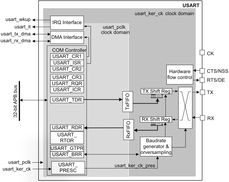
Block Diagram
This is how UART is laid out on the STM32H7RS, though a lot of this is so fundamental it'll be similar/identical on other chips.
The image is below, and it tells us a lot of things already:
- you'll find the configuration registers on the APB bus
- there's an interrupt and DMA interface for non-blocking software design
- the image is nicely divided into which parts are controlled by the bus interface clock and which by the kernel clock (if you're not sure what this is, read up on the RCC article)
- the TxFIFO/RxFIFO are connected to the shift registers, which are clocked by the baudrate generator (baudrate generated by kernel clock)
- all of that leads to the
TX/RXpins you use to talk over UART
Note that not all USART/UART/LPUART instances support a kernel clock. Where they don't, usart_ker_ck is tied to usart_pclk and the peripheral only uses 1 bus.
The TX pin isn't always 'there', if you aren't configuring UART with the transmitter enabled, this becomes a normal GPIO pin. If configured, the pin idles at high when no data is being transmitted. There are also 2 interesting UART modes called single-wire and smartcard. I won't talk about the latter in this article, but single-wire lets you transmit and receive over a single wire, and this is the pin used in those modes.
The only other thing worth mentioning in terms of pure UART is the pin labelled with NSS - that is for UART in synchronous master-slave mode, and it's used as input for slave selection.
The other pins are not so relevant as they're for other protocols that use the UART block as their base. They need separate articles.
* Not all chips include these 3. The STM32H7RS, for example, does - but typically you'd only have the first 2. LPUART is only really on chips with low-power use cases in mind, and the H7RS as that one just has everything. Writing this sentence led me to learning that ARM doesn't actually manufacture the ARM Cortex-M core, they just provide the license for manufacturing. Companies like STMicroelectronics take it and make their own version by expanding its functionality and having it manufactured. Not very useful info but at least you're prepared for semiconductor trivia night!
UART Characters
On the STM32, you can specify how long you want the data field of the UART package to be. You can typically choose between 7, 8, or 9 bits, which is selected in the USART_CR1 control register.
By default, Tx/Rx are both low during the start bit and high during the stop bit(s).
If a period the length of a full UART package is all 1's, that's interpreted as an idle character*. If a period the length of a full UART package is all 0's, that's interpreted as an break character. From my research, it seems like these are user-defined, as in they can be detected and you can choose what to do on each of them.
* Although they're called 'characters', they aren't the typical 8-bit ASCII character you might be thinking of. They're just a period of time equivalent to a full UART packet where the signal is all 0s or all 1s.
FIFO And Thresholds
By default, UART is configured to use the USART_RDR and USART_TDR registers for receiving/transmitting data 1-byte at a time.
This naturally comes with issues, such as:
- the CPU has to handle every read/write directly, so it wastes CPU cycles that could've been used doing something more productive
- you can only read 1 transferred data packet at a time, with each new one overriding the old one, which leads to data loss if you aren't fast enough in servicing it
With FIFO mode (FIFO standing for "First In, First Out"), you can have the chip automatically sending/storing packets until it hits a threshold, in which case you are made aware through an interrupt. And you usually do use FIFO mode with interrupts (unless you have a specific reason not to, such as specific timing requirements).
The reason it's called FIFO is because it works like a queue: the first packet you receive from UART is the first one serviced when you read the data buffer, and the first packet you put in the buffer is the first one that gets sent i.e. it keeps the data in the same chronological order.
FIFO mode is entered through the setting of the FIFOEN bit in the USART_CR1 control register, and you can only use this mode in UART, SPI, and smartcard modes (only discussing UART in this article).
And since the data you can send/receive is able to be up to 9-bits wide, so the TxFIFO is 9-bits wide.
However, the RxFIFO is 12-bits wide as it needs to store 'metadata' flags:
- parity error
- noise error
- framing error
Despite this, when you read USART_RDR, you only read the 9-bits of data without the flags, which can be read from USART_ISR.
FIFO Threshold Interrupts
As for the threshold levels, it's possible to configure both the Tx and Rx levels at which the interrupts are triggered using the USART_CR3 control register, looking for the RXFTCFG and TXFTCFG bits.
In the Rx buffer, the threshold is reached when the USART_RDR register and the RxFIFO hit a combined total of the threshold. Since USART_RDR has a capacity of 1, the threshold is hit when the RxFIFO is at threshold - 1 amount of data stored.
Additionally, the Rx flags are only set one time once the threshold is reached, NOT for every individual transfer.
In the Tx buffer, the threshold is reached when the number of 'empty' data locations is greater than the threshold value.
UART Transmitter/Receiver
You don't always want to send data over UART, sometimes you want to only read.
That's why you need to enable the transmitter first if you want to send data, which is done through the TE bit located in the all-so-versatile USART_CR1 control register.
In the same way, you don't always want to send data, and USART_CR1 also has a RE bit to enable/disable the receiver.
Transmitter TE
Disabling the transmitter through the TE bit during the sending of data is going to corrupt the data permanently (as in, even re-enabling it later won't recover the interrupted transfer).
When enabled, the TE sends an idle frame. This is the only way I've seen outlined that guarantees the sending of an idle frame.
Transmitter Default Vs FIFO
The way data is sent is always the same:
- LSB sent first
- data is shifted and sent via the shift register
When sending data without FIFO mode, the USART_TDR register is the only buffer between the internal bus and the shift register, which means the send needs to happen and finish before filling the register up again, otherwise you will lose data.
When sending data with FIFO mode, the data you put in the USART_TDR register gets queued in the TxFIFO.
Upon sending this data, it preceeded by a single start bit that corresponds to a logical '0' (as per the UART protocol), and by a configurable number of stop bits (again, as per the UART protocol).
The RM0477 reference manual (and possibly reference manuals for your board) has an outlined sequence of how to bring up the transmission part of UART and send data.
Transmitter Flags
There are a few flags you get access to, summarised from the RM0477:
| Flag | Meaning | How To Clear | How To Enable |
|---|---|---|---|
| TXE | Transmit data register empty | Write to TDR\* | TXEIE |
| TXFNF | Transmit FIFO not full | Fill TxFIFO | TXFNFIE\*\* |
| TXFE | Transmit FIFO empty | Write to TDR or write 1 to TXFRQ | TXFEIE |
| TXFT | Transmit FIFO threshold reached | Write to TDR\*\*\* | TXFTIE |
| CTSIF | Clear-To-Send interrupt | Write 1 to CTSCF | CTSIE |
| TC | Transmission complete | Write to TDR or write 1 in TCCF | TCIE |
| TCBGT | Only for smartcard mode | n/a | n/a |
* In FIFO mode, TxFIFO needs to be full as well. Not a confirmed reason that I found or anything, but I believe this is because the USART_TDR contents get moved to the TxFIFO buffer in FIFO mode unless the TxFIFO is full, and this flag only checks if the USART_TDR register has contents inside it, not the TxFIFO.
** When you enable the FIFO (FIFOEN = 1 in USART_CR1), the TXEIE/RXEIE bits get replaced with their FIFO counterparts - TXFEIE/RXFEIE. The two never co-exist at the same time. They exist on the same bit of the register, they're just interpreted differently based off FIFOEN. I only realised this when I started writing code for my UART drivers and questioned why there are two USART_CR1 and USART_ISR registers with one labelled [alternative].
*** Writing to TDR will only cause the flag to be cleared if the empty spots in the TxFIFO are less than the threshold. It remains set otherwise.
Break Characters
You can manually send a break character to the UART stream by setting the SBKRQ bit. Its length depends on how many data bits you're using.
When the bit is set, the current transmission finishes before the break is sent - this includes FIFO mode; even if TxFIFO is full, the break character still takes priority.
Unless I didn't explain it clearly earlier: when you send a break character, it guarantees the receiver to recognise the next start bit (synchronisation).
UART Receiver
Just like the transmitter, the receiver needs to be enabled to work, as you won't always need to read data.
On the STM32, the UART receiver is enabled through the RE bit in the USART_CR1 control register.
Once enabled, it will receive data of length 7, 8, or 9, depending what you've set (just like the transmitter).
Receiver Flags
As with the transmitter, there are flags that trigger interrupts on various events:
| Flag | Meaning | How To Clear | How To Enable |
|---|---|---|---|
| RXNE | USART\_RDR not empty\* | Read RDR or write 1 to RXFRQ | RXNEIE |
| RXFNE | RxFIFO not empty | Read RDR until RxFIFO is empty or write 1 to RXFRQ | RXFNEIE |
| RXFF | RxFIFO full\*\* | Read RDR | RXFFIE |
| RXFT | RxFIFO threshold reached | Read RDR | RXFTIE |
| ORE | Overrun error detected\*\*\* | Write 1 in ORECF | RXNEIE/RXFNEIE |
| IDLE | Idle line detected | Write 1 to IDLECF | IDLEIE |
| PE | Parity error detected | Write 1 to PECF | PEIE |
* Only set when the data is ready to be read.
** Asserted once both USART_RDR and RxFIFO are full.
*** An overrun is when the UART receiver runs out of space in the RDR and causes new packets to result in data loss. Applicable to FIFO mode, too, except it only happens when the RxFIFO fills up first. Note that new data doesn't overwrite old one, instead it is simply lost (newest data currently received is stored in the shift register, that's about all).
Start Bit Detection
Oversampling as a concept was outlined in an earlier section, this section expects familiarity with it.
On the STM32H7RS, the UART controller samples the start bit at the following intervals:
- 3rd, 5th, 7th
- 8th, 9th, 10th
Across both sample groups, if 3/3 samples are detected to be a logic-low (corresponding to bit 0), the RXNE/RXFNE flag is set.
If only 2/3 of the samples are detected to be 0, the start bit is still validated and the RXNE/RXFNE flags are still set, however the NE (Noise Error) flag is also set.
If any less than that is sampled and determined to be 0, the receiver aborts the start bit detection and no flags are set.
Character Reception
During reception, bits are shifted out of the shift register LSB-first.
Special character handling:
- when a break character is received, the UART controller handles it as a framing error*
- handled in the same way as other characters, except the IDLE flag is set and the interrupt is generated
If you are looking for how to configure the receiver, there's likely a detailed step-by-step in your reference manual (at least in the RM0477 there is).
* A UART framing error is what happens when the receiver detects that the packet format has been violated and isn't following what was expected. More specifically, the RM0477 reference manual says the framing error flag is set when the stop bit isn't received/recognised at the expected time.
Mute Mode
If you're using UART as part of a network where multiple controllers share the same UART lines, you can configure mute mode.
This mode causes the receiver to ignore incoming data that isn't addresses at it. It puts the receiver in a pseudo-sleep state where flags and interrupts won't be set for incoming data, unless it's the intended recipient.
The way UART knows it's this intended recipient is in one of two ways:
- Idle line detection
- Address detection
The former listens for an idle character (all 1's sent through), which generally would wake up all nodes on the network and get them ready to receive the next message.
The latter compares the incoming character against the ADD bits in the USART_CR2 register. If it matches, it wakes the receiver up, otherwise it's ignored to save processing power. This can obviously wake up one or multiple nodes, depending on how you configure their addresses.
Clock Selection
Prior to letting any clocks affect the UART block on the STM32, you need to enable it with the UE bit in the USART_CR1 control register. Leaving it disabled keeps the UART in low-power mode, where the prescalers and outputs are all disabled*.
The clock you select must fit these 2 criteria:
- Possible to be used by UART in low-power mode
- Have a fast enough communication speed (for baud rate and oversampling)
The actual line you configure in tools like STM32CubeMX is the usart_ker_ck line, as this is regarding the kernel clock (see the RCC chapter if the term 'kernel' clock is unfamiliar).
Where needed, there is a configurable prescaler that feeds into the UART peripheral, and it's configurable through the USARTx_PRESC bits. It lets you slow down the kernel clock, and the clock it outputs is called usart_ker_ck_pres.
As mentioned earlier, not all UART peripherals support a kernel clock, and so not all peripherals support low-power functionality. Where they do, however, this allows for you to set UART up in a way that it collects data in low-power mode, and only wakes the MCU to perform data processing.
* Note that you should (not must) wait for any transactions to finish before shutting it down, otherwise you will see errors on the line.
Oversampling
The OVER8 bit lets you select if you want to use 8x or 16x oversampling.
If you want:
- a higher maximum clock speed, 8x is better
- more clock deviation tolerance, 16x is better
Sampling Amount
The ONEBIT lets you select if you want the bit to be sampled 3 times and averaged, or just sampled once.
If you are:
- in a noisier environment, 3 samples are better
- in a noise-free environment, 1 sample is better as it's more resistant to clock deviations
Note that in 1-sample mode, the NE (Noise Error) flag is never set, as it needs an average of multiple samples to be weighed.
Baud Rate Deviation Tolerance
In order to avoid issues, the overall deviation of all sources has to be less than the maximum allowable USART deviation tolerance, which you can find in your reference manual. The STM32H7RS tolerances are shown below from tables 562 and 563.
IMGS
To calculate your actual deviation, you need to add up the following values:
- DTRA: deviation due to transmitter*
- DREC: deviation due to receiver*
- DQUANT: deviation from imperfect quantisation of receiver baud rate
- DTCL: deviation due to transmission line
- DWU: deviation due to sampling point moving around after a low-power wake-up (see formula below)
DWU formula
DWU = tWUUSART / (Mbits * Tbit)

// tWUUSART is the time between a start bit being detected and the clock being fully started up clocking the peripheral (so this is after a wake up)
// Mbits is your data length + 2
// Tbit is the duration of one bit on the UART line
* This includes its local clock fluctuations.
UART Baud Rate Generation
This might just be the most confusing part of UART on the STM32, mostly in conceptualising the maths behind it. So bear with me while I try to explain it.
UART Auto Baud Rate Detection
I'll be honest, this sound a lot better than it is. There are only really 2 uses for it:
- you somehow don't know the communication speed of the other device in advance
- the other device has a low-accuracy clock, making it simpler to auto-detect baud rate than calculating deviations
It goes without saying that your board must be capable of the expected* communication speeds of the unknown device.
* I say 'expected', which is where the "sounds better than it is" comes from: you can't just set a magical "detect baud rate" bit and have it work flawlessly. You need to have an estimate of what the unknown device's UART speed will be, as the auto-detection needs to be in the rough ballpark to work, and even then it can fail.
To enable auto baud rate detection, you need to set ABREN and the ABRMOD bits in the USART_CR2 control register. It allows you to select between 4 modes.
Additionally, the value in USART_BRR must be set (not 0).
Mode 0
Any character starting with a bit at 1.
Here, the ABR detector continuously samples for the starting bit and then samples for its duration.
Mode 1
Any character starting with a 10xx bit pattern.
Here, the ABR detector checks for the 2 edge changes (starting bit to 1, and 1 to 0), which the reference manual claims is more accurate.
Mode 2
A 0x7F character (in MSB mode, 0xFE instead).
Just like mode 1, it samples for 2 falling edges, but in this case it's the falling edges of the end of the start bit, and the end of bit 6.
Mode 3
A 0x55 character.
In this mode, the packet is sampled at different speeds:
- BRs: first speed, updated at the end of the start bit, bit 0 sampled at this speed
- BR0: updated at the end of bit 0, bits 1-6 sampled at this speed
- BR6: updated at the end of bit 6, bits 7+ sampled at this speed
At the same time, in parallel, another check is done using the baud rate guesses to see if the edge transitions are where they're expected to be. If not, then the guess is clearly wrong and an error is raised.
In all modes, the checks are ran multiple times and compared against the previous one to ensure accuracy and consistency.
Upon finishing, the ABRF flag is set in the USART_ISR register. If an error needs to be raised, the ABRE flag is set alongside.
Auto baud rate detection can be ran again by clearing ABRF.
Note that in FIFO mode, the detection must be made using the first RxFIFO data location, so the RxFIFO must be emptied before starting the process.
UART Single Wire Mode
When stated as implemented, the UART peripheral can connect its TX and RX pins internally, and run UART with just 1 wire.
This of course means that when one device is talking, the other can not also talk, and the same applies for listening. This is called half-duplex communication, where communication can only ever happen in one direction at any one time.
As the TX pin will only ever be idle or in service, it must be configured in its alternate function mode, open-drain, with external pull-up enabled (see GPIO article if this doesn't make sense).
The RX pin is simply disconnected.
Single-wire mode is enabled in the USART_CR3 register by setting the HDSEL bit. In that case:
- LINEN/CLKEN must be disabled (
USART_CR2) - SCEN/IREN must be disabled (
USART_CR3)
The rest of the protocol is similar to regular UART, you just need to make sure your firmware manages conflicts in the line (aka don't send when receiving).
UART Receiver Timeout
If you want to be notified (via an interrupt) when the UART receiver hasn't received anything for a certain amount of time, you can set a timeout.
On the STM32, the receiver timeout functionality can be enabled through the RTOEN bit in the USART_CR2 register.
The way it works is it starts counting ’baud periods' (derived from baud rate: 9,600 baud rate means you get 9,600 baud periods per second, so 1 baud period is 1/baud_rate), where the point it starts counting from depends on how many stop bits you have have configured:
- 0.5 stop bits: from the beginning of the stop bit
- 1/1.5 stop bits: from the end of the stop bit
- 2 stop bits: from the end of the second stop bit
Once it starts counting, if a new start bit isn't detected within the timeout duration, the RTOF flag in the USART_ISR register is set and an interrupt is called if RTOIE is set in USART_CR1.
The timeout duration itself is configured in the USART_RTOR register. The lower 24 bits dictate the ’baud periods' before a timeout is detected, therefore the max amount of baud periods is:
(2^24) - 1
That's also the max size of an unsigned 24-bit integer.
Note that if your board doesn't support the feature, the RTOR register is forced to 0x00000000 by hardware and can't be changed.
Low-Power Mode UART
In low-power modes, the UART peripheral can continue to function, and on the Nucleo-STM32 boards it's also capable of waking the MCU up via a wake-up interrupt, usart_wkup.
This is useful functionality due to the fact that in low-power modes, the bus clock (usart_pclk) can be turned off. However, in order to send/read data, you need access to the RDR/TDR registers - and registers are controlled by the bus clock.
To enable waking up the MCU, you first need to set the UESM bit in USART_CR1.
Once you go into a low-power mode, what happens depends on the FIFO configuration.
Without FIFO
Any data that gets received must be serviced directly and immediately to avoid overrun errors. Therefore, the usart_wkup interrupt source is set to be the RXNE bit (table further up the page outlines meanings of these)
This also means you need to set RXNEIE prior to entering low-power.
With FIFO
In this case, the usart_wkup interrupt source will be one of these, as per your configuration:
- RXFNE
- RXFF
- TXFE
- RXFT/TXFT
In all of these cases, their enable bit xIE has to be set.
If you instead want, you can use the WUS bits to select the wake-up source. It's in the USART_CR3 register and can be configured to use one of these for wake-up:
- address match (using ADD & ADDM7 bits)
- start bit detection
- RXNE/RXFNE
The WUS are part of the WUF functionality, which needs to be enabled by the WUFIE bit to work. Enabling this causes interrupts to be generated even when the MCU is in RUN mode, not only in low-power.
UART Safety
There are a few best practices when using UART with low-power modes to ensure it all functions properly.
First, make sure no transfers are currently ongoing when entering low-power mode. It is not sufficient to just check the BUSY flag though.
Also, if you just initalised UART and want to enter low-power mode, wait for the REACK bit in USART_ISR register to be set. It reflects that the RE bit to enable the receiver has been acknowledged by the UART block, otherwise you may not get wake-up interrupts sent through.
If you're using DMA, make sure it's disabled for the duration of low-power mode.
If you're using FIFO, waking up from an address match (WUF enabled and selected through WUS) is only possible if the receiver is in mute mode. You also can not wake up with the receiver in mute mode using idle detection, as it’s disabled in low-power.
Kernel Clock Requests
When the usart_ker_ck kernel clock is off in low-power, the peripheral can request it when needed.
It requests (usart_ck_req signal) a kernel clock when a falling edge on the receive line is detected.
The kernel clock is then used for the frame reception, and there are 2 options:
- wake-up event verified: MCU wakes up from low-power
- wake-up event not verified: usart_ck_req is released, the kernel clock switches off again, and the MCU does not wake up
Post Wake-Up
| Mode | Effect |
|---|---|
| SLEEP | No effect on UART. Any interrupt wakes MCU up from sleep. |
| STOP | UART register contents kept. Only able to wake up when clocked by an oscillator available in STOP mode. |
| SUSPEND | UART powered down, reconfiguration is needed upon waking up. |
UART Interrupts
I included most of these earlier, but here they are again.
Transmitter Interrupts
| Flag | Meaning | How To Clear | How To Enable |
|---|---|---|---|
| TXE | Transmit data register empty | Write to TDR | TXEIE |
| TXFNF | Transmit FIFO not full | Fill TxFIFO | TXFNFIE |
| TXFE | Transmit FIFO empty | Write to TDR or write 1 to TXFRQ | TXFEIE |
| TXFT | Transmit FIFO threshold reached | Write to TDR | TXFTIE |
| CTSIF | Clear-To-Send interrupt | Write 1 to CTSCF | CTSIE |
| TC | Transmission complete | Write to TDR or write 1 in TCCF | TCIE |
| TCBGT | Only for smartcard mode | n/a | n/a |
Receiver Interrupts
| Flag | Meaning | How To Clear | How To Enable |
|---|---|---|---|
| RXNE | USART\_RDR not empty | Read RDR or write 1 to RXFRQ | RXNEIE |
| RXFNE | RxFIFO not empty | Read RDR until RxFIFO is empty or write 1 to RXFRQ | RXFNEIE |
| RXFF | RxFIFO full | Read RDR | RXFFIE |
| RXFT | RxFIFO threshold reached | Read RDR | RXFTIE |
| ORE | Overrun error detected | Write 1 in ORECF | RXNEIE/RXFNEIE |
| IDLE | Idle line detected | Write 1 to IDLECF | IDLEIE |
| PE | Parity error detected | Write 1 to PECF | PEIE |
'Other' Interrupts
These are the rest that I haven't mentioned yet, including whether they're relevant or not:
| Flag | Meaning | How To Clear | How To Enable |
|---|---|---|---|
| LBDF | LIN mode, not relevant | n/a | n/a |
| NE | Noise error | Write 1 in NECF | EIE |
| ORE | Overrun error* | Write 1 in ORECF | EIE |
| FE | Framing error | Write 1 in FECF | EIE |
| CMF | Character match** | Write 1 in CMCF | CMIE |
| RTOF | Receiver timeout | Write 1 to RTOCCF | RTOFIE |
| WUF | Wake-up from low-power modes | Write 1 to WUC | WUFIE |
| UDR | SPI-slave mode, not relevant | n/a | n/a |
* The OVRDIS bit in the USART_CR3 register has to be set to 0 for this flag to work as explained.
** A character match is the same as an address match, the UART block looks for incoming characters that match what's inside the ADD bits in the USART_CR2 register, triggering an interrupt when detected.
Sources
CircuitBasics - Basics of UART Communication StackExchange - UART oversampling STMicroelectronics - STM32H7RS Reference Manual StackExchange - How does the UART communication detect the true idle in this case? Wikipedia - UART Microchip - Guard Time ComputerHope - UART Overrun Wolfchip - What is the UART data framing error? DeepBlue Embedded - STM32 UART Half-Duplex Single Wire Tutorial & Examples STMicroelectronics - STM32H7 USART Presentation